An architecture description for guidance system test cells
The problem
The Trident II D5LE2 program is modernizing the MK 8 guidance system, which is integrated and verified across a family of test cells that each support different test types between unit acceptance and system-level qualification. Before System Functional Review (SFR), the program needed to show it was building the right test cells by running a gap analysis between test cell requirements and design, and that analysis needed a description of each cell connected well enough to follow a requirement through the scenarios that exercise it to the equipment that supports it.
I took over the modeling lead almost as soon as I joined the effort, when the team that had started the model was reassigned, and did the modeling from then on, which meant building that description while correcting traceability in the inherited model that couldn’t carry the analysis.
Constraints
SFR expects a baselined functional architecture, preliminary allocation, key scenarios exercised, and traceability demonstrated but not exhaustive, so I modeled to that bar and marked placeholders where coverage would mature at PDR and CDR, with four test cells prioritized for SFR and four deferred. The unit under test (UUT) is an external black box defined by an interface control document (ICD) that the design authority owns and revises, so the model had to represent those interfaces faithfully without authoring them. Every view also had to be extractable as a static document for stakeholders who couldn’t open the model, and program modeling standards governed naming and structure so the model could federate with others.
What I did
Four views per test cell
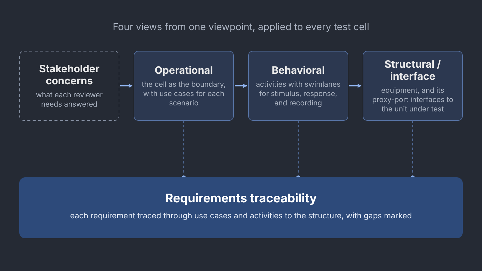
I structured the architecture description under ISO/IEC/IEEE 42010 around one program viewpoint that every test cell’s views conform to, with the viewpoint and its relationships held in the model rather than only described in a briefing, so each cell gets the same four views:
- Operational: the cell as the system boundary, with the UUT, support systems, and people as actors, and use cases for the major verification scenarios.
- Behavioral: activity diagrams with swimlanes for the cell’s subsystems and the UUT, carrying stimulus, response, evaluation, and data recording.
- Structural/interface: the cell’s equipment and how it connects to the UUT.
- Requirements traceability: requirements traced through use cases and activities to the architecture, with gaps marked.
I chose these four because each answers a question some stakeholder brings to a review, and because together they form the chain a gap analysis walks, in which concerns drive scenarios, scenarios decompose into behavior, behavior is allocated to structure, and requirements trace through all of it. The stakeholder-to-concern mapping I briefed at SFR shows which views answer which concerns:
| Stakeholder | Concern | Answered by |
|---|---|---|
| Navy customer | Verification confidence, compliance evidence | Traceability |
| I&T team | Sequence clarity, equipment allocation, operability | Operational, Behavioral |
| Program management | Schedule, coverage status, risk visibility | Traceability |
| Prime contractor and design authority | Interface alignment, ICD compliance | Structural |
| Quality assurance | Process compliance, witness points | Behavioral |
| Software team | Test automation integration and scope | Structural, Behavioral |
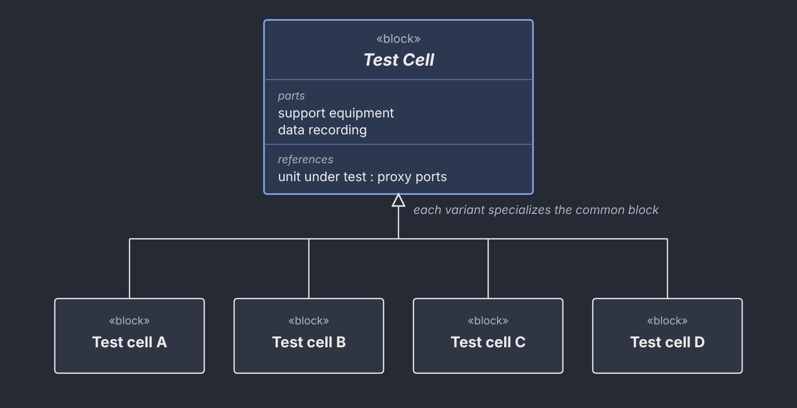
One viewpoint across the family keeps the cells comparable and lets shared content be written once, and a family-level block definition diagram shows each cell as a specialization of a common test cell block.
Stakeholders, actors, and use cases
I modeled stakeholders as elements that generalize to abstract actor roles and consolidated roles that overlapped in practice so the actor set stayed small enough to reuse. Pre-test and post-test sequences that every cell shares became common use cases each cell includes, and I wrote use case specifications for the four priority cells with entry and exit conditions, a main success scenario, and only the alternate flows that mattered, with assumptions marked for subject matter experts to confirm.
UUT interfaces as proxy ports
I modeled the UUT’s interfaces from the ICD as proxy ports typed by InterfaceBlocks, because at SFR a proxy port states the interface contract without committing to internal structure, which suits a UUT the I&T team doesn’t design and test equipment whose internals were still maturing, and I left full ports for PDR and CDR.
Traceability semantics
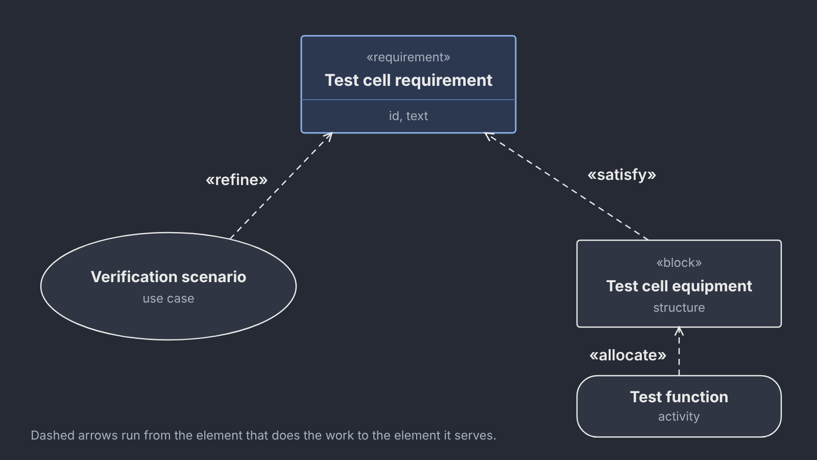
The inherited model linked requirements to use cases with a generic trace dependency running from requirement to use case, which records a relationship without saying what kind and runs opposite to a use case elaborating a requirement. I moved the model to the conventional SysML pattern, in which use cases refine requirements, blocks satisfy them, and functions are allocated to blocks, and I staged that refactor inside the SFR window, because every view built on the old links would have raised the cost of changing them, and I have since completed it.
A HWIL facility outside the family
I also wrote a use case specification for a flight avionics hardware-in-the-loop facility the program provides to the prime contractor, and since its interfaces were still being defined, I wrote it as a working draft for requirements sessions with the facility team, separating actors from stakeholders, tiering the actors, and tracing each use case to the facility’s requirements.
How I knew it worked
I proved the method on one test cell before asking anyone to apply it across the family, briefing reviewers through a live walkthrough that followed one scenario from use case through activity and interface diagram to the requirements matrix, with the draft items named up front. The lead engineer for I&T endorsed maturing the method across the family, and it has since been applied to the other three priority cells and carried into SFR.
The gap that mattered most sat downstream of the test cells, because test planning and V&V planning weren’t using the model. A separate V&V model is now being stood up to build test analysis cases, and under the approach I proposed it will reference the I&T model and the design authority’s guidance system model rather than copy from them. I have no quantitative coverage measure to report, so the evidence is the endorsement, the adoption across the priority cells, and that downstream use.
What went wrong and what I learned
Preparing the SFR brief was where my own approach needed the most correction, because my first version explained the method in the abstract, with worked examples promised for later, and cited 42010 without showing the stakeholder-to-concern-to-view chain the standard asks for. I rebuilt it around one test cell walked end to end, added the concern mapping, the family taxonomy, the interface view, and a risks section, and kept the traceability refactor in backup material so the method and the semantics decision could each be judged on their own terms.
I came away convinced that reviewers are persuaded more by one scenario they can follow than by coverage they have to take on trust, and that naming draft items as expected builds more credibility than defending them. If I started again I would build the walkthrough first and write the framework around it, and I would bring the test and V&V planners into the model at the outset instead of learning afterward that they weren’t using it.
An example you can look at
The test cells and their specifications aren’t public, so here is one invented scenario carried through the same views, for a power-on functional test of a generic unit, with nothing in it drawn from the program.
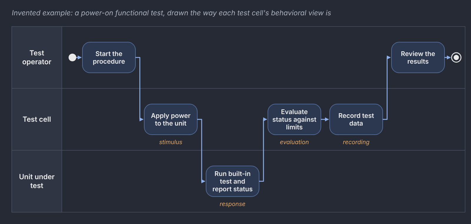
The use case specification that drives it follows the same template as the priority cells, with only the alternate flows that matter.
Use case: Run a power-on functional test (invented)
- Primary actor: Test operator. Supporting actors: the test cell and the unit under test.
- Preconditions: the unit is installed and connected through its interface adapter, and the test cell has passed its self-check within the last day.
- Main success scenario:
- The operator starts the procedure.
- The test cell applies power to the unit within its input limits.
- The unit runs its built-in test and reports status.
- The test cell evaluates the status against the limits for this test type.
- The test cell records the test data against the unit’s serial number.
- The operator reviews the results and closes the procedure.
- Alternate flow 4a: the status falls outside its limits, so the test cell removes power, records the failure, and flags the unit for review before the operator continues.
- Postconditions: the test data is recorded and traced to the requirement it verifies.
- Traceability: the use case refines the invented requirement “The test cell shall verify the unit’s built-in test status at power-on,” which the power supply and data recorder blocks satisfy.
Artifacts
The models and documents themselves aren’t public, so these figures show the method with generic content and no program data.